The XO-1 is the same diff. As a 100mph 1/7 scale does that mean it has crappy 1/10 MT diffs or does it mean Traxxas 1/10 MT diffs are that robust/capable? They even use the same case. Both are two planetary gear setups/one shaft. The other two are the sun gears. This is how the ECX 2wd is, how most RC diffs seem to be, and how most 1:1 stuff is. As opposed to the ECX 4wd stock diff, which has 4 planetaries and 2 subs. I can’t access the old thread linked on ECX 4wd diff failures, any chance anyone remembers what in particular failed about them? Hopefully not the housing or the case LOL looks like those must be reused.
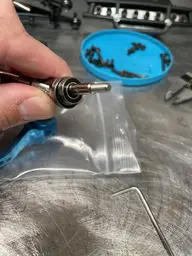
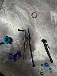
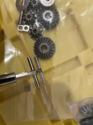
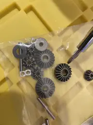
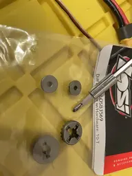
Losi diff internals arrived. They are close, but not in any way the same. In each of these pics the screwdriver indicates the ECX part. Different diameters on sun and planetary gears. Different pin lengths. Different depth on planetaries. Different pin setup for planetary to outdrive.
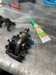
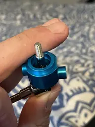
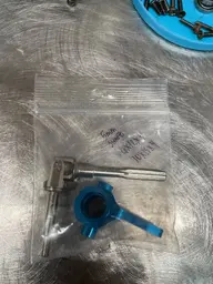
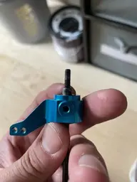
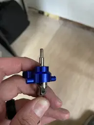
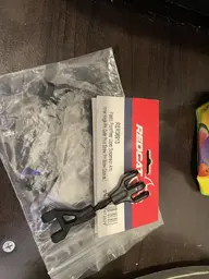
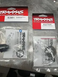
Some more Traxxas parts arrived to explore swapping the entire Traxxas diff/ring/pinion into the ECX housing. This would absolutely require front and rear be done as it would change the gear ratio (39T ECX ring, 37T Traxxas). Both 13T pinion. Pinion of Traxxas same shaft diameter but single piece probably would require custom center driveshaft.
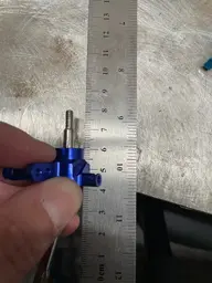
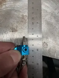
Ring diameter 38mm ECX 37.5mm Traxxas
Diff width out to our 31.40 ECX 32.08mm Traxxas
Bearing journals (for diff bearing ID) 12, 12 ECX 8, 10 Traxxas. ECX diff housing has two 18mm journals for bearing OD
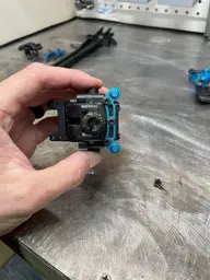
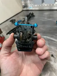
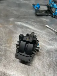
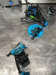
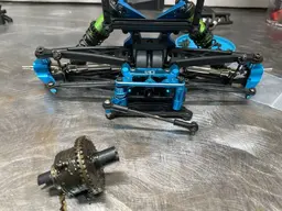
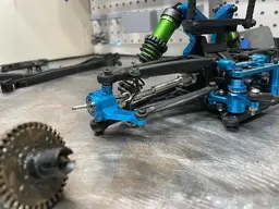
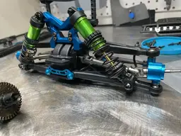
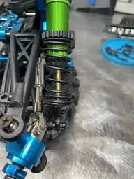
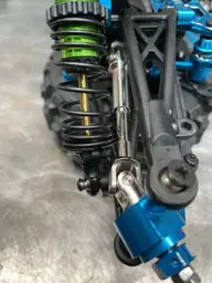
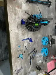
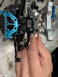
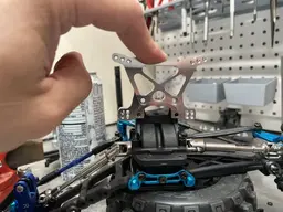
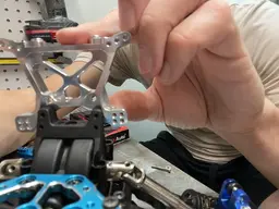
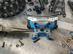
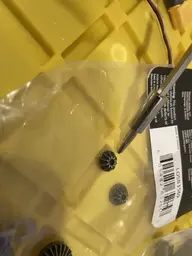
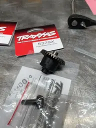
Some pics of my Traxxas guts in ECX diff installed in a ECX housing. I only had one 12x18 bearing on hand. Next pics of Traxxas diff in same housing. I think this is as far as we go before killing the idea. Pinion too far into housing to attach anything to its end for the center driveshaft. Diff too wide for housing are first major hurdles. No way to shim it for R/P mesh.
We tried. I guess a backup idea for now is if I can’t get the Traxxas spider gears to work well in an ECX diff, just put the Traxxas out drives in it and weld it as a spool. Not ideal, but not unheard of either. Better than a permanent 3WD shelf queen


Losi diff internals arrived. They are close, but not in any way the same. In each of these pics the screwdriver indicates the ECX part. Different diameters on sun and planetary gears. Different pin lengths. Different depth on planetaries. Different pin setup for planetary to outdrive.
Some more Traxxas parts arrived to explore swapping the entire Traxxas diff/ring/pinion into the ECX housing. This would absolutely require front and rear be done as it would change the gear ratio (39T ECX ring, 37T Traxxas). Both 13T pinion. Pinion of Traxxas same shaft diameter but single piece probably would require custom center driveshaft.
Ring diameter 38mm ECX 37.5mm Traxxas
Diff width out to our 31.40 ECX 32.08mm Traxxas
Bearing journals (for diff bearing ID) 12, 12 ECX 8, 10 Traxxas. ECX diff housing has two 18mm journals for bearing OD
Some pics of my Traxxas guts in ECX diff installed in a ECX housing. I only had one 12x18 bearing on hand. Next pics of Traxxas diff in same housing. I think this is as far as we go before killing the idea. Pinion too far into housing to attach anything to its end for the center driveshaft. Diff too wide for housing are first major hurdles. No way to shim it for R/P mesh.
We tried. I guess a backup idea for now is if I can’t get the Traxxas spider gears to work well in an ECX diff, just put the Traxxas out drives in it and weld it as a spool. Not ideal, but not unheard of either. Better than a permanent 3WD shelf queen
Attachments
-
 E708A3BD-F277-4EF4-AD8F-BAB59624497C.webp30.1 KB · Views: 2
 -
 72D8FDA6-404F-43C5-8E97-39AF232FEA61.webp37.7 KB · Views: 2
 -
 336AAC1A-DF2E-4D95-9F38-370B444D7212.webp35.1 KB · Views: 2
 -
 B65DE7DE-C0ED-478C-A7EF-C587695B6DD2.webp39.4 KB · Views: 2
 -
 DC9BB8B8-6A29-4913-91F4-EF219B18E34C.webp94.2 KB · Views: 2
 -
 A518571D-F12F-40B7-BE49-37F0B9F741A0.webp66.5 KB · Views: 2