1/10 4WD build

Aluminum hubs for the Prolines came in...mmm...
00403A8D-4EC1-4498-BAFE-CDFCE01958E3.jpeg


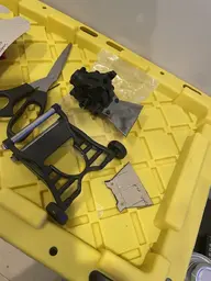
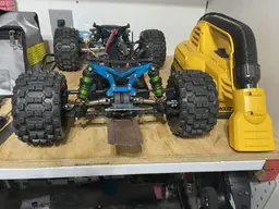
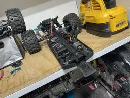
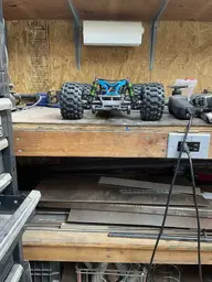
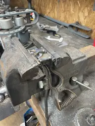
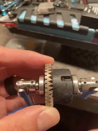
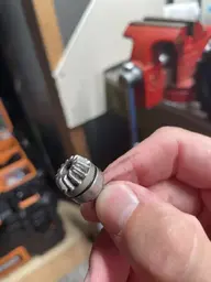
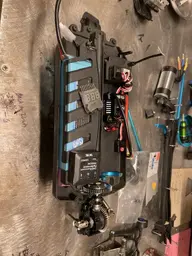
What to do after FINALLY getting this thing working again after being depressed looking at a shelf queen and seemingly insurmountable project for months? Tear the rear apart, duh! Took a couple pics for reassembly reference.
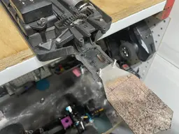
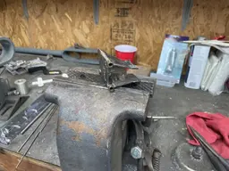
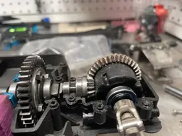
3D80CD03-0B12-44FC-B6C1-E18829C9D701.jpeg5AA347FA-53FD-4107-A9F8-594B104FEE10.jpeg99A06FA5-8A2C-4099-929F-7EBFD0480ECE.jpeg


stock rear guts
92E59DE3-A711-4D45-8D0B-C1E6E9CA112D.jpeg


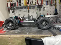
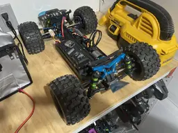
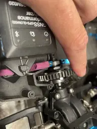
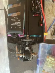
I have the benefit of having that other rear prepared clean and ready to drop in, so lazy me is going to use a new housing too I'll bag the old one and clean it later. More of me just trying to justify that huge lot of 4WD parts I purchased.

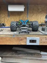
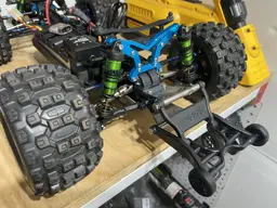
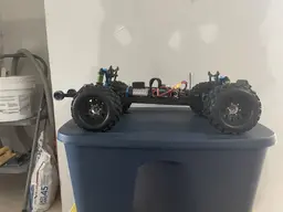
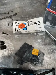
Just quickly looking at the RPM arms versus the stock ones I'm going to have to do the same thing I did in the front of the vehicle, so I just checked to see if I had the room to move the front pin brace forward instead of the rear pin brace backward (into the rear bumper). No go, sorry.
B2D36FDA-5A6D-4550-BA99-73EE48D1FAE0.jpeg


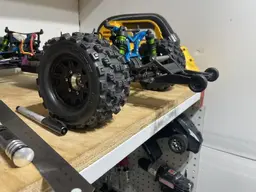
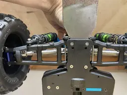
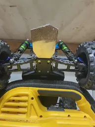
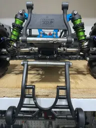
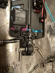
The next issue is during disassembly I came across this...I verified they were installed correctly, and there's no adjustability. I mentioned before in some top down shots and when I aligned it that there was some rear toe in, but it seems to drive okay like that. Honestly when I took the stock stuff off I didn't measure the rear toe, but I save everything that's not blown to smithereens so I dug up the old pin braces and all 4 stock ones are the same length...because they are adjustable. They use inserts that can be run in 4 different orientations (per side) to give different toe settings. Not really sure why you'd want to run either of the top settings. There is an arrow that indicates the position of the pin from the outside (viewable side). Comparison pic, HR units next to stock ones front down and in rear down and out next to stock ones both front and rear down and out (zero toe). HR ones overlay the stock ones perfectly. I considered just ordering up a second set of the HR ones and mix and match, but the pin holes in them are actually drilled on the needed angle so that wouldn't work.

The hubs I ordered (2 different sets) can impact rear toe, so I found some info on the slash 4x4. So ideally I would like to set this up with 2.5* toe in.

  • The Traxxas Slash 4x4 has 2.5 ° of toe built into the rear bulkhead.
    The stock plastic carriers have 0 ° of toe.
    The aluminum carriers have 1.5 ° of toe.

    2.5 ° + 0 ° plastic carriers = 2.5 °
    2.5 ° + 1.5 aluminum carriers = 4.0 °
    2.5 ° + reversed aluminum carriers (-1.5 °) = 1 °

    Reversing the plastic carriers does nothing. You will still have 2.5 °

E7CEF98D-CF54-47DB-923A-F16581DCAC5A.jpegF55C8B8F-B3C0-4B01-A065-998F49C82DAF.jpeg43CBDE94-A325-49AA-AA7F-5A849B33F43D.jpeg

With both adjusters pointing down and in, pin to pin is 43.3mm outer 37.5mm inner (40.4mm center of pin to center of pin). With both adjusters pointed down and out, pin to pin is 47.7mm outer 41.9mm inner (44.8mm center of pin to center of pin). Pin length installed is 41.0mm between the pin braces, but the LCA is 41.5mm wide so we will go with that. So that makes for a right triangle with one side 41.5mm and the base 2.2mm (half of the two center to center difference). So tangent of the toe angle is 2.2/41.5. So, 3.03 degrees of toe in if I did my trig right. Somewhere a teacher from 20 years ago is proud.
 

Attachments

  • 7937D3A4-DE56-4291-AD3F-FF24AEE1F822.jpeg
    7937D3A4-DE56-4291-AD3F-FF24AEE1F822.jpeg
    190.6 KB · Views: 1
Last edited:
Here's your parts and part numbers (some)
8449B8E8-A6CD-4B67-B29E-1467FC75FF3D.jpegDEE17D57-BF10-47A8-8B6C-78B7D1A7518C.jpeg


After doing the front, I knew the place to start was the lower control arms. Here is the ECX versus the Slash one. I measured 4mm difference in width at the inner pin. By the time I got everything mock up assembled, I verified that I needed 4mm of spacer at the back of the rear diff housing and 4mm longer pins (stock is 51.5mm).

70108CC6-65EA-44BB-AD3E-38767FDECAED.jpeg1CDE075E-64F4-409A-96DA-C67720FA2889.jpegB2A78456-23F9-4C9F-A359-597D899BDC25.jpegE995C387-6527-464E-B8E0-83647AA63E6E.jpeg


You may have noticed two sets of rear hubs pictured before. the "skinner" ones are the Slash 4x4, and the more robust ones are from the XO-1. While I was researching axles to make sure I had upgrade options in the future, I ran into people commenting that the XO-1 was the only rear aluminum upright that works with the large diameter almighty Tekno 6mm rear axles. I doubt I would be able to use those axles (they are a dogbone inner CVD outer fixed length axle what I swapped away from in the front), but I'm all about that bigger bearing life. The Slash uses a 5x11x4 inner and outer rear bearing, which I have a history of being very hard on (especially inners). The XO-1 uses at 6x12x4 inner and outer. You will need to run a conversion bearing 5x12x4 to use the axles I pictured (or pony up $64.99 plus shipping to be the guinea pig and try the Teknos). Side by side comparisons of the hubs. That is the conversion bearing pictured in the XO-1 hub.
74947D3F-0BC2-4A5A-BE65-E34F27C59413.jpegBF878ACD-F121-4CA0-9E3D-B015749A2D2E.jpeg

ta-da. I am installing left on left and right on right which should set toe to -3.5 degrees. Keep in mind I have set the static toe back to zero with the rear toe adjustments at the pin (currently, I can go in or out).
B4B6767D-F7DE-426F-AA47-7CAF8345B3DA.jpeg9B24F0D2-21DD-4E0B-A7C7-63A749E51608.jpeg
 
Last edited:
got some new washers to shim the planetary gears (3x8x0.8), so here is how I'm currently running them. 10k diff oil for the rear, superglued ring gear bolts
6BCA20C5-0BDA-4D68-9BB6-BF8BC7ED95F1.jpeg33E55A15-19A5-4B5B-A85F-250FE637626D.jpeg11F904D8-EC7F-490D-897B-6DBB8B418940.jpeg


Cut some new LCA pins from 3mm stainless stock, pretty simple if you have some sort of cutting device and a file.

7AA02B98-45D3-48F6-9E3F-D4AB73822FDC.jpeg2B5DA607-75E8-48F2-8694-2A011E06BA98.jpeg02025BBE-91FC-49F9-92CB-9C57F2A6299E.jpeg


All mocked together. I have a bunch of cobbled together spacers for the 4mm spacers between the housing and the rear pin tie bar so I have some on order, but it looks like this crazy plan just might work.
15DF1733-49C5-46CA-B5EB-F29DD51248B6.jpeg66CB29E2-AE10-4878-9027-FA6BC7173181.jpeg7A742FF5-34FE-4D93-9F2C-7793E51AC987.jpeg832CCCB5-D9F4-48F9-B414-7069A3F5DF28.jpeg
 
Last edited:
Today I began by receiving the 4mm spacers in the mail, which I ended up supergluing to the actual housing to make future assembly/disassembly easier. The outers required just a touch of trimming to clear the inserts of the rear tie bar.

3ABA2F2A-98C0-4639-B600-5D2F478FA2E0.jpeg


I didn't go quite as nuts with the grease this time, it was getting all over the RC (and nearly into the clutch plates of the slipper).

5DDD1658-B3AD-413A-8B49-D1BBB7C1E67E.jpeg


Final assembled views of the rear end.
FFAFD696-E8CA-4CA2-8DF0-5DAF98F2B9A7.jpegDCAD5165-090E-4205-9E3C-281A55F12249.jpeg


Quick alignment, then off to walking around the yard. I ended up moving the lower shock points and adjusting the rear shocks to get the lower control arms level and then adjusting the camber again. I didn't measure the rear toe to verify it's -3.5 as it's supposed to be...yet. For a "monster truck" this thing is pretty low, which is awesome.
207D5755-E43B-46E4-948B-905323D25890.jpeg506B75ED-15DC-4895-B32D-6CE646EA53B5.jpeg36F010D3-A5FE-4AD4-8386-1E0E6FD4FCB6.jpeg


First time out on 2S only two problems was lost the left front wheel nut and the wheel hex pin when the wheel came off. Pretty easy fix. Had some well worn old nut on there for all the mock ups I've been doing is the likely cause. I have some fancy ones coming as big power this seems to be a reoccurring problem. The other was sudden drivetrain noise, progressively louder, quick inspection nothing obvious sounded slipper/motor then loss of forward propulsion altogether. Turns out the motor twisted in the mount which is how the pinion/spur mesh is set, so the pinion actually moved far enough away from the spur there was an air gap in between! Look at the orientation of the motor wires...how I had it set was almost at 12 oclock!

4D6C6996-D375-48FD-A426-14FFF2F77592.jpeg56A4123A-E1D4-42F6-940A-2CB7AB5C0CAC.jpeg

I ended up ditching that spring on the motor mount bolt and just going to a plain washer and loctite on both. I put two witness indexing marks on the motor and the mount so I know if it moves again.
 
Last edited:
7C9C291E-4D92-483B-87A5-BB8E0D005F65.jpeg

The only other battery I had ready was a 100C 3S, so whatever. Seems to work really well. The rear definetely acts like a locker, I'm interested what 30k in the front diff is going to do, especially with some Badlands up there. One thing I forgot for my cardboard to-do list was on full left turn the steering shaft STILL hits the driveshaft (to the point it will stop the front wheels).

Did one speed hit through the grass, didn't want to go crazy it was really tall. They make a belted MX28 which this thing really needs on 3S. The gyro makes me look like an absolute hero on gravel


Attachments

  • 484AC166-524B-4D52-A3DA-0EC2B313C2C8.png
    484AC166-524B-4D52-A3DA-0EC2B313C2C8.png
    96.7 KB · Views: 1
Last edited:
So far, motor hasn't moved again
9FC65051-22C3-42C4-AF5E-83E35FD6A22C.jpeg

Redid the steering idlers AGAIN, and it finally clears the driveshaft completely lock to lock. Going to run it for a bit to ensure, I'd be willing to bet the driveshaft moves around a good bit since both ends are that dogbone/cup style. I had to end up dremeling out just a bit of clearance on the backbone/spine to give the arm a little more room. I may need to do similar for the idler underneath, we will see.

2AABF12B-F56D-4DE3-91C1-1CE144C44C89.jpegC2516F78-3E0D-4861-A0A6-C3408C9E56ED.jpeg


I don't remember taking a hard hit to the front left, but apparently I did because the LCA pin is bent. Can't tell if the arm is permanently bent or that's just how the pin is sitting and/or if the H-R pin braces are bent (seem to be). I'll get that junk out of there when I re-do the front. I cut some new pins today so they are ready whenever I get around to it.

F494065A-F8F0-4469-A4A9-29F5D6C095CC.jpegF18886DD-3AF4-44D6-B7F9-07C516E86600.jpeg


Last item was to cut up the front fenders, clearance issues to the front corner of the body when turning, both sides. Even with the body at the highest position. Tried to cut it in a way that followed the body lines and trimmed for the front lights while I was at it. Took off that awkward back corner by the back bumper that catches everything too, may cut more for less parachute back there. After cutting, we were able to get the body back down low how I like it. Overall, just enjoyed it today. Drives really well on grass with Badlands at all corners, it's a pretty good truck now for his age and ability. I think we are just going to enjoy it for awhile and put some miles on it as is.

DCDF3E5E-20FB-439E-807B-FFC98C269134.jpeg12A89527-18D5-4D0B-8BE1-E1CB9B9656CB.jpeg80F5E2A7-CF92-4F11-AAAB-BEE4908EB8E6.jpeg551203BC-2045-42F0-BB0D-7D288941F5FD.jpegEF27953B-431E-4459-8D71-47B5946E27AE.jpeg
 
Last edited:
Monsoon here today so put some work in on remaking the wheelie bar mount. 1/8 plate 4mm x 6mm tube spacers

It made it easier to template the lower by removing the rear subassembly. It’s kinda sad how quick I can have this thing apart these days.

Tack welding without lighting the car on fire is a challenge. I think I got it where I want it, I need to come up with some bracing between the upper and lower to keep it from twisting. I wanted the lowest wheelie setting to be parallel to the ground and at the chassis height, like the 2WD turned out
 

Attachments

  • A3E77DEB-EF2C-4C40-99CB-323CE8EC0FA2.jpeg
    A3E77DEB-EF2C-4C40-99CB-323CE8EC0FA2.jpeg
    112.9 KB · Views: 1
  • 626E1B25-4282-4C05-ABF2-5425C2FEFE27.jpeg
    626E1B25-4282-4C05-ABF2-5425C2FEFE27.jpeg
    268.8 KB · Views: 1
  • 1243041B-BF6B-4E84-A3A9-F3E2202A9115.jpeg
    1243041B-BF6B-4E84-A3A9-F3E2202A9115.jpeg
    185.7 KB · Views: 1
  • 0749A1F9-008A-4071-9216-E311E12C2A2A.jpeg
    0749A1F9-008A-4071-9216-E311E12C2A2A.jpeg
    167.5 KB · Views: 1
  • 10E4A73A-D748-4615-8AFF-0A68EE0E9148.jpeg
    10E4A73A-D748-4615-8AFF-0A68EE0E9148.jpeg
    213.3 KB · Views: 1
  • 4D35E2A4-3D4F-4FF2-B33B-B8A177C6EF72.jpeg
    4D35E2A4-3D4F-4FF2-B33B-B8A177C6EF72.jpeg
    188.1 KB · Views: 1
  • 2F2E379E-F01E-405E-AEB4-85769EA48197.jpeg
    2F2E379E-F01E-405E-AEB4-85769EA48197.jpeg
    130.6 KB · Views: 1
  • EFAF2566-28DE-4BBA-8149-E4E546747475.jpeg
    EFAF2566-28DE-4BBA-8149-E4E546747475.jpeg
    207 KB · Views: 1
  • 008F8F38-295F-422E-B373-A981E1457144.jpeg
    008F8F38-295F-422E-B373-A981E1457144.jpeg
    229 KB · Views: 1
  • 4B5F7A2C-DFEE-435D-9961-A73087A40BC2.jpeg
    4B5F7A2C-DFEE-435D-9961-A73087A40BC2.jpeg
    237.3 KB · Views: 1
Got the lipo upgrade for the X6. Seems to work fine in the house LOL

66524CA0-264F-46E0-9A7D-EACEE3114D55.jpeg
 

Attachments

  • 1879F587-17B2-4A22-876B-058E1A2146B6.jpeg
    1879F587-17B2-4A22-876B-058E1A2146B6.jpeg
    140.3 KB · Views: 1
  • E69F6FC8-7C1D-42BD-A46C-83EB356BC22B.jpeg
    E69F6FC8-7C1D-42BD-A46C-83EB356BC22B.jpeg
    217.4 KB · Views: 1
I’m no award winning welder. I think it needs more bracing between the two pivot points. I wonder if the ride height change is from the mounts weight.

A4598794-AB72-4E21-ACFF-6B2C38416695.jpegD273090A-66DB-4AB3-BF6E-7AD2811279E7.jpegE27AD6B5-5D4F-4BB0-8615-F233DD514179.jpeg
 

Attachments

  • 632B16E4-918E-4C01-88DD-4596CC6F5F2B.jpeg
    632B16E4-918E-4C01-88DD-4596CC6F5F2B.jpeg
    204.3 KB · Views: 0
  • 55B09FCE-F776-444A-B2A3-115EF857DCCB.jpeg
    55B09FCE-F776-444A-B2A3-115EF857DCCB.jpeg
    139.1 KB · Views: 1
  • 3E7ECEED-7A65-4C36-BCD6-1EC0AD55CF75.jpeg
    3E7ECEED-7A65-4C36-BCD6-1EC0AD55CF75.jpeg
    200.2 KB · Views: 1
Last edited:
Finished welding it, seems to work just fine. Not award winning, for sure. Definitely need to adjust the suspension to account for the weight. Ordered the same rubber wheels I put on the 2wd wheelie bar.

Noticed another bent pin, this time in the rear. I don’t recall hitting anything major, and beginning to wonder if it’s an issue with cheap stainless steel

DB7556AE-348E-4C2C-B6EA-FCD8233EEEB9.jpeg
 

Attachments

  • 6204E66B-3B49-47BF-B56C-6B22947C3778.jpeg
    6204E66B-3B49-47BF-B56C-6B22947C3778.jpeg
    216 KB · Views: 1
  • 24AADC6C-9E7C-400A-B010-D5586FE78BB3.jpeg
    24AADC6C-9E7C-400A-B010-D5586FE78BB3.jpeg
    158.6 KB · Views: 2
  • 83BC1A61-F438-4175-B611-4C991F1CFAB2.jpeg
    83BC1A61-F438-4175-B611-4C991F1CFAB2.jpeg
    344.8 KB · Views: 2
So the belted 2.8s finally came in, and for whatever reason they are a much narrower short course style than the regular (non-belted) Badlands. Kinda disappointed, but I got them on a deal and for what return shipping and restocking would cost me I'm just going to keep them. Tossed them on the front since I think there's way more grip up there than is needed at this point anyway mind as well take the weight break. It actually looks kinda cool like this. RPM toe gauge came in so I was able to align it. It's a nice piece, but honestly a metric tape measure is better if you're dealing with knobby tires like this.
CEE3A0FF-6943-4C60-A3E9-1038952A3D11.jpeg96B334BE-9ADC-4D0C-82DE-1A71A40F779E.jpeg


My son, 3, decided to try and satiate one of his younger brothers (twins, 3 months) by giving him one of the old tires. The baby got quiet so I assumed he had put his binky back in like he normally does, until I came out to see this.

15CC8128-F484-4039-B8A7-1F53B37196B5.jpeg


Rubber tire upgrade for the wheelie bar.
57989B59-D210-4B5A-8DA3-283B5C602B08.jpeg


Replaced the rear pin that was bent (with another one of the same). I was very careful to keep the heat down this time when cutting and grinding the new one to size, we will see if that makes any difference. Fortunately, the bent RPM arm sprung back into place once the bent pin was removed. I ordered some tungsten carbide stock to try if this problem continues. I just did the rear quickly because it was so easy to pop the wheelie bar off and the back pin brace and slide the pin out quickly.
7C0F6B89-D3ED-43B9-B8A0-DDF5D2F565EF.jpeg


Fancy schmancy wheel nuts that were touted on the internet to be all that and a bag of chips came in. Installed on the rear with the aluminum hubbed wheels, and, along with some loctite, have ended the loosening problem (especially left rear).
5CD9A06C-7177-4728-9733-956A016971EF.jpegA74A93EC-476C-49E5-8470-29C85351B5C7.jpeg


Took it out yesterday and drove it a bit...you know what, it is a lot better with those narrower tires up front. The Bandlands are still such a good compound and tread design it has traction for days (for what power makes it up front anyway), and the narrower diameter it turns in a lot better too. Whether the narrower or the belted helps I'm not sure, but no more pizza cutter front wheels under full power.

Took it out today, and having it completely dialed and right where we want it, I just had to mess with it. This ESC is listed at 2-4S and people are claiming to run 4S all the time on this combo (despite motor saying 3S), so I hooked up two of my 2S in series and sent it. I had just cut the grass today, and it was hot and dry, if there was any time to make a banzai pass this was it. It was MOOOOVING, 36mph on partial passes on grass, really needing to pick my lines to avoid the rough stuff and wheelies. When it suddenly kicked hard right and died completely. Motor hot, ESC hot, wire T hot. Figured I hit the temp sensor cutoff for the motor, let it cool, nada. ESC fan works, radio receiver works, steering works, motor doesn't. ESC doesn't beep or light any LEDs when you power it on, or ever. Troubleshooted on bench using a good known motor, nada. Known good ESC with the hobbywing motor works fine, so at least I just grenaded the ESC not the motor too. Bought it in April, well out of warranty, Hobbywing tech support was quick to help me with some diagnostic attempts. Explored my options on the internet tonight - bigger Hobbywing ESC, different brand, etc. and ended just ordering another of this one up. This was its first time on 4S, but in terms of how hard or how long or how hot I ran it, we weren't anywhere near as hard as I've pushed this before on 2S or 3S. I've hit the overtemp cutoff a couple times in the same day. Bummer. I'm learning grass is really, really hard on parts.

8D68F995-E95A-4FF3-8D7F-25D2BBEA5B42.jpeg
 
Last edited:
I looked back in this thread and think I found the mistake...swapped the XT90 connector that came on the ESC for a deans connector. Apparently not as good. Also, I thought this was a 3200kv, it's a 4000kv, which is right on the edge of the 3S rating. People were putting the 3200kv to 4S, and not on grass. What likely happened is the motor drew more current than the ESC could handle.

Took advantage of amazon prime day, and ordered a proper 4S 100C battery that will fit the shorter tray I have with a XT90 on it so it can plug in with no adapters and a 3674 2950kV that's rated for 4S. I've had good success with a 3674 2250kV in the 2wd Ruckus on 3S, so why not? Gonna send this thing to the moon (or more likely turn the differentials into dust). I do lose motor overheat sensor as it's not a Hobbywing motor :-(

Part of me just wanted to put a Max 8 and a 4274 in it and try to rotate the Earth.
 
Got new motor and replacement ESC in today. Hobbywing wants the old one back despite it being out of warranty period (by a lot).

14B2388E-C205-46DA-AAC0-9F92B07768F5.jpeg
5DB810E4-78D8-4AA4-83CD-892DB49C490E.jpeg10AE164F-FC24-4042-976E-CCBAF75C2046.jpeg
3FF60390-4F73-4D48-BAC2-6BBF35B501DC.jpeg

Just broke it in on 2S today. The 4S hasn’t arrived yet. I ran it for 4-5 hard passes and the motor wasn’t even warm to the touch. I’m going to put the 3S in it tomorrow and raise up the ride height to try and clear the grass some. The stock brushless truck did 11mph on this surface.

5D03EB13-65C4-4754-92E4-A81566B7B77B.jpeg
Look what came at the end of the day. First charge went well.

1AD4E3AB-8E0B-4DB3-930D-546B5F5C2C58.jpeg
Had to drill out another Phillips screw out of the motor plate (I went to SS Allen this time). One of James twin brothers on my lap trying to help.
 

Attachments

  • 9B166196-3C12-45D5-84E5-856BD5BCB990.png
    9B166196-3C12-45D5-84E5-856BD5BCB990.png
    86.8 KB · Views: 1
Today was full of ups and downs. I tried to get back to back runs in on 2S 3S and 4S and minimizing as many variables as possible. The grass has just been cut and it’s really dry. Other than being hot and humid (90F), better grass conditions for speed can’t really be had. All runs on fully charged batteries, same radio, same ESC, same motor, same gearing. I tried to repeat the same warm up pattern for each run, run the same line, and each had a 2-3 hour cool down between (that is more life with 3 kids than anyrhing else).

Yesterday it went 22mph breaking in the new motor on 2S 100c. Before I did anything today I warmed it up with a few part throttle figure 8s and tried to establish a race line I could repeat - and confirmed the 22mph. It looked like it was really pushing through the grass so I raised the ride height as much as I could in the front and then brought the rear up to match the ride height. I didn’t believe it picked up 3mph just from that! All future runs were done at this ride height.


F2BF9CCE-45A1-4306-93B2-B2D2573E8650.jpeg60A08603-93A3-40C1-8CCE-D897684888DF.jpeg


Put the 3S 100c in it, and managed 34mph. It’s all over the place at speed and constantly getting up on the wheelie bars especially over any bumps…so we ended up putting it right into moms raised planter bed. He’s only 3 so he drives with me helping so I’ll take the blame. Ouch. I’m just glad no expletives came out on that one.


94D07B74-D751-4334-815D-5F4334F6BBEF.jpegCDDA2399-FABA-47D8-9342-CF8B5B6CE22A.jpeg5337C4E1-8D51-4B10-BF6F-46A348AD8958.jpeg91EEAD9D-BF11-48E6-8741-568148AF7A4D.jpeg
 

Attachments

  • D9E1D2D6-06A5-4BBD-8367-BFE96F7EA274.jpeg
    D9E1D2D6-06A5-4BBD-8367-BFE96F7EA274.jpeg
    32.9 KB · Views: 0
  • 1B58CAF8-F90F-4543-97B2-561C103274E7.jpeg
    1B58CAF8-F90F-4543-97B2-561C103274E7.jpeg
    32.9 KB · Views: 0
I got to work during nap time. I already had cut replacement pins, the control arm bounced back into shape once the bent pin was removed (the pin hole is a little slotted now so I should probably replace it anyway). Replacing the HR crap aluminum pin braces was already on the list so I said screw it and just bent it back into shape removing the front diff is like an entire day job.

12FD5F70-5326-4ACE-A4BE-7D88C46DC66A.jpeg3C6DF877-C03D-4825-99D3-15F72558442C.jpeg


The GTR shock is obviously gone but I was able to rig up a bunch of preload on something I had to get the correct ride height.

9C265742-5385-4C94-8176-87B95199B460.jpeg62D46DA2-B809-4CEF-8D82-B5DD662404CD.jpeg


I was hoping the camber rod I had just popped the end loose - that must be the strongest plastic on earth to outlast the aluminum center section - I had a replacement.

BB1A8C3F-AEBC-4A37-932B-E16A85704433.jpeg


Somehow knocked the upper caster block bolt completely out!

0421AAA7-0D61-4A06-B7BF-BDC39D31D844.jpeg


Got it all back together, did a quick camber setting. Went back out and ran it again and actually took a few tries to get back to 34mph I had a bunch of 30s…I think I’m running out of room and out of courage to use that room after that hit. Made a change the front was 1 degree toe out I changed it to 1 degree toe in to try and give it some more high speed stability. Ran it again to verify it didn’t change speed, still 34mph. Also went from the mx28 belted (skinny) on the front to the wide badlands with the aluminum hubs on the front and put the wheelie bar on its lowest wheelie setting to try and get the front end down and ran it back. Still 34mph, front a lot more planted. I think it’s trading off the front end being down and not constantly riding the wheelie bar for the extra mass of the bigger wheels and having to push that wider drag through the grass. When we go to 4S I’ll run it back to back with both wheels.


88B4E3E0-C4F5-4F59-A0A6-DCDBFF1DA7D1.jpeg
 
4S 100c was underwhelming as hell. I know law of diminishing returns, but I hoped to be somewhere 38-39mph, maybe more once this brand new pack breaks in. How it feels and sound is rowdy as hell.


When I looked at the GPS I really couldn’t believe it. 35mph. I started looking for problems. Motor and ESC are still relatively cool. Pinion/spur mesh is a hair loose but nothing crazy, making it really tight solved nothing.

6108AB9D-1A42-4044-8414-43B3320B1200.jpeg20E8A444-E5E9-4C10-BD22-197B8B5667BD.jpegF4969A2A-06EA-4E34-9903-CD5194214700.jpeg

Found the rear diff input drive (pinion flange on a car) snapped a tooth off. Did it happen on 4S or was it like that, who knows? Seemed to be a logical reason to lose a bunch of speed if it wasn’t getting power to the rear wheels. Took it back out, didn’t seem to change, and after 3 or 4 hard hits, the slipper was so bad I lost all forward movement. Let it cool down and tried to tighten it full tight while still in the car, nope.

Took it out on the bench, pads have completely spun, totally glazed over. I run it 1/6 turn from full tight, pretty darn tight setting. Keep in mind these are relatively new pads, they were pure white when installed. I did my gasket material/150 grit to plates/superglue pads setup I did in the 2wd after struggling with pad issues and took it back out as we were losing sunlight…only to have the same horrible slipping sound after one 35mph hit

808C1DD1-AD1C-4872-A353-A53AD2C7F6FD.jpeg589E528F-FE8C-4578-BE5F-127A2534407E.jpeg17203573-18C1-4397-9003-087F455FE55D.jpeg3301F8AE-B8EE-4D35-9294-14AF1BED4ABB.jpeg


The slipper plates look like absolute ass and I’m not sure if I can get them yet (I can get pads). I think what I’m going to do is make a slipper eliminator and see if there is any mph difference. It’s possible that 4S power plus how much drag the grass is putting on the drivetrain the slipper just doesn’t have the clamping force/friction to hold up. If I see a gain from the eliminator on 4S I may just throw the 3S back in there to see if we were losing anything at the top end. Another thought I had was reducing the drag by going to the skinny MX28 belted on both front and rear. I’ll have basically zero traction down low but if I find a bigger space and slowly ramp into it, it may mph better up top having to push less grass out of the way.

Just for a point of reference how tough grass is, the old 3s combo 3662 4000kv did 26-27 on grass and 50 on pavement…zero changes, the same badlands off-road tires and all. That’s part of what is so cool about it for me is it seems like no one is trying to do it…1/10 scale on grass
 

Attachments

  • 4E282F3A-35DF-461C-B08D-27BBF4408C87.jpeg
    4E282F3A-35DF-461C-B08D-27BBF4408C87.jpeg
    33 KB · Views: 0
  • 5B1AD5AA-CF24-4ACF-8D42-DD6AE4EBE8FA.jpeg
    5B1AD5AA-CF24-4ACF-8D42-DD6AE4EBE8FA.jpeg
    33.1 KB · Views: 0
Gonna send this thing to the moon (or more likely turn the differentials into dust).

It would seem I am pretty good at foreshadowing.

96F190F3-7285-44D6-9E64-C1AADF4964D7.jpeg76DCF9E7-EB05-4AAA-A1FE-2DA22CAB437B.jpeg2DC66F1D-BE9B-4905-8F99-94A718CC21C5.jpegBBE0D372-1EF9-4FD5-97C0-17507FD0356A.jpeg
Made my own eliminator by putting new pads in to try and square everything then cranking the nut all the way tight and drilling and through bolting the clutch plates and the ring gear. I had a bunch of ideas how I was going to do this but figured this to be the least permanent way. If you’re doing this, I’d probably ditch the spring entirely in favor of washers.

Hard to explain, but I tried to tighten up the free play in the center driveshaft by moving the slippers front cup forward. In this pic it still shows there is 7-8mm free play. What I didn’t account for is it tightens up when you put the center spine back on, to the point it binds the drivetrain. Had to blow it all back apart and put it back against the front bearing where it was before
0D3344C3-66EA-48FC-8BE3-B1A0F19F1A58.jpeg


Took it out with the slipper eliminator and warmed it up, WOW. Violent is the word I could best describe it as. Instant wheelie beyond 50% throttle at any speed. Trying to make a full pass was just one long wheelie with the front tires ballooning. I thought the wheelie bar was pretty impressive going over uneven terrain at those speeds kept it up but stable (not torquing to one side and cartwheeling like our 2wd). Made 3 or 4 just trying to get a clean run in and noticed it down on power and shortly after No forward power. Tear down basically took every tooth off the front pinion and sheared the left rear wheel hex pin. My assumption is from the continued front end going up and down under power with the slipper eliminator shocked the drivetrain over and over. Had so little runtime, didn’t even get a video. Despite how violent it looked and how fast it felt, it only did 32mph…being on the wheelie bar and turning it into rwd only isn’t a good way to go fast.
139DA303-4339-4989-A5AA-A503B2D67B9A.jpeg
189B9EBC-DD23-4F12-A3B1-0DD96D26B245.jpeg


Put a new front pinion in this morning (ring looked okay ish at quick glance, lowered the front, raised the rear as high as I could and moved the shock position to a harder angle (trying to keep the weight on the front and keep it from shifting it to the rear under power).
 

Attachments

  • 61D0BD96-21DB-41D3-80C6-781CCF84A692.jpeg
    61D0BD96-21DB-41D3-80C6-781CCF84A692.jpeg
    108.4 KB · Views: 0
  • 2D18BB1D-710D-430D-9B5B-45A5EA24E7A7.jpeg
    2D18BB1D-710D-430D-9B5B-45A5EA24E7A7.jpeg
    84 KB · Views: 1
Last edited:
Made sure to get video when I went out this morning. Turned punch in the ESC all the way down to try and help antiwheelie too. Glad I did, because it didn't survive long. Looking back over it a few times, watch and listen around 0:14 the first time it sets the front down after a wheelie. Pop noise, and from that point the drivetrain noise changes and progressively gets worse.


I was 1 on 3 with the kids all day, my wife was sick so I didn’t really have too much time to play but I did get it torn down. Immediate failure was breaking another rear diff output cup at the back of the slipper, but when I took the rear end apart to replace it, I found the rear pinion and the rear ring with parts of teeth gone, as well as the front part of the rear diff housing broken off (the bearing support)

0E28233C-912C-4476-9510-3572E759206C.jpeg


A reasonable man would conclude that a sheared wheel hex pin, two sheared rear diff input cups, two toasted clutch slipper pad sets, two pinions, one ring, one diff housing (and counting…I still haven’t opened up the front diff) would be this truck telling me that 4S is a no-go. A reasonable man would also look at his dwindling pile of unicorn replacement parts and consider the increasing risk of turning this into a paperweight with each breakage.

…I’ve been known to be less than reasonable.
 

Attachments

  • C7E68734-FD57-4F26-8791-D08CE0F32F3F.jpeg
    C7E68734-FD57-4F26-8791-D08CE0F32F3F.jpeg
    161.1 KB · Views: 0
  • C1981A38-F1DD-4AD6-8093-2CB7C4033EB0.jpeg
    C1981A38-F1DD-4AD6-8093-2CB7C4033EB0.jpeg
    89.3 KB · Views: 0
  • CF1F6FD8-3498-445B-8B7A-EEC77FCCE8A1.jpeg
    CF1F6FD8-3498-445B-8B7A-EEC77FCCE8A1.jpeg
    173.8 KB · Views: 0
  • 569BA345-66AE-456D-93DD-EE90BF1011E8.jpeg
    569BA345-66AE-456D-93DD-EE90BF1011E8.jpeg
    75.4 KB · Views: 0
  • D5E7FDF3-A3AC-44F7-BFE9-5FA41CF2C808.jpeg
    D5E7FDF3-A3AC-44F7-BFE9-5FA41CF2C808.jpeg
    113.9 KB · Views: 0
I didn't realize you were running this thing on 4s! These things barely handle 3s without diff issues I'm surprised it lasted as long as it did.

Been trying, still on the fence about it. My ultimate goal was to build a 50mph grass basher that was easy to drive and could take any abuse a 3 year old could throw at it. We've managed the second two of those goals.

Took the front apart today in the little time I had (mom still sick), seems okay since that one time it shaved the teeth off (to be fair that was also immediately after that bad drivetrain bind I described so who knows. So I need to figure out a solution for the rear differential and the slipper/spur and the rear pinion flange that keeps shearing off. Before even my seemingly endless pile of spares runs out.

AE6B51E8-FDBB-47C8-83D4-6F854D101D59.jpeg5DEF957C-EB3C-497B-8253-112D1718420F.jpeg


I'm getting entirely too good about tearing this thing down. If you look close, you can see where my insane brain is going for a solution. The broken nose of the rear diff housing makes me think there is some deflection going on from torque under power and that's causing the R&P to come out of mesh (which is why it chips the edges of the teeth off first). If I can stop the deflection, maybe the R&P will hold up...maybe it's also just a metallurgy problem and nothing short of getting a billet R&P will help.
 

Attachments

  • 0F62409D-82DD-4BB0-8C5D-1BECAFBDD25F.jpeg
    0F62409D-82DD-4BB0-8C5D-1BECAFBDD25F.jpeg
    184.3 KB · Views: 1
  • 0C3D0D44-DA86-42B1-90D0-D3051D2FB839.jpeg
    0C3D0D44-DA86-42B1-90D0-D3051D2FB839.jpeg
    129.7 KB · Views: 1
Last edited:

Latest posts

Members online

No members online now.
Back
Top