95PGTTech 1/10 2WD ECX Ruckus build

After reaching out to MIP...
From the MIP install instructions https://www.miponline.com/assets/images/mip-inst-18140.pdf

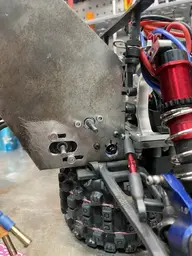
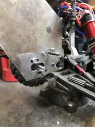
Previously I had installed neither of these spacers because this is not a Traxxas Slash install and the rear hub seems to have a machined face that the rear wheel bearing sits against. These are XO-1 rear hubs, which are for all intents and purposes "hopped up" Slash hubs, so I did test install the 2mm spacer (blue arrow I added) this time since I had it on hand anyway. It fits, and it spaces out the *inner* races of the rear wheel bearings. I put the 1mm spacer (red arrow), and removed the 0.5mm spacer I had previously between the outer wheel bearing and the hex nut. With the hex nut cranked down as hard as I can now, the whole assembly rotates completely free like the front, and there is zero play in and out. MIP engineers 1, me 0. I still did not install the 2mm spacer they have shown at the inner most end of the axle to the transmission. This is for spacing on a Slash and would need to be much, much thicker to serve the same purpose on our longer differential output drives.

2022-10-19.jpg


Rear wheels now spin free of any binding whatsoever (all the way back to the spur gear). Very nice, tight product compared to other axles I've used. Big thank you to MIP for these and their tools that we use (and their tech help time). This set of axles I have is an older set, as the picture depicts it uses the obsolete inner hub design. They clarified that it's just an issue of a change in manufacturing they made and I don't need to go replacing the inner hubs unless I manage to break one, there is no performance or reliability difference between the new design and the old design.
 
Playing around with mod1 gears on the AX10 trans.
IMG_6302.JPEG


SSD Wraith transmission arrived. It reuses the stock 20T input (top shaft) gear, but a different idler and final drive to give a transmission ratio of 1.80 - much better than the ECX stock and AX10 stock 2.60. I did attempt to put one gearset into the other and it won't work, you can't put a 1.80 gearset in the "stock" trans. The motor plates on each are very slightly different because of the case differences and the hole pattern is different for the same reason, so they are not interchangeable.
IMG_6303.JPEGIMG_6305.JPEGIMG_6306.JPEGIMG_6309.JPEG


The Wraith has an extended output on what is our driver side, so custom axles would be in order to use it. Although the SSD case is very nice, it lacks the brass knob on the back of the trans - this allows you to tighten up and eliminate any in/out play in the top shaft, which is an awesome feature. I did not measure the weight difference, but the SSD is noticeably lighter. A couple grams is not of a particular concern to us.
IMG_6307.JPEGIMG_6304.JPEGIMG_6308.JPEG


The carbon slipper pads did arrive for the 48p spur, I need to get another so I have one to glue to. I feel like we are about at the limit of what the combo has to offer. Yes, we could probably spend a few months fine tuning things and making little improvements here and there, but the motor is beginning to get hot at these gearings and we are limited to plastic spurs at this rate. Even a conversion to 32p wouldn't help, there just isn't the big ratios we need readily available.

Kinda let the cat out of the bag on FB, but I think this accurately sums up our next move.
IMG_6313.JPEGIMG_6312.JPEG
 
The $10 wait a month from China motor plate doesn't fit *exactly* or maybe I'm just too picky. It came with three huge 10mm spacers to give it clearance to the housing. I chose to drill out the center hole to allow the plate to slide back further and rest on a couple areas of the case itself. The three bolt holes also got drilled out to 3.5mm because they didn't exactly line up. I needed 7 washers (.5mm ea)to achieve what I was content with

IMG_6319.JPEGIMG_6318.JPEGIMG_6317.JPEG


Red and tacky for lube for all my transmissions. A variety of mod1 gears arrived.
IMG_6333.JPEGIMG_6314.JPEG


I modified the stock ax10 top shaft with a divot where I could put the set screw for the mod1 spur gear (it's really a pinion gear, but I'm using it as a 30T spur)
IMG_6329.JPEGIMG_6330.JPEG


Packaging is always a hurdle on a 1/10. Even for something that's really just an engineering test run and a lot of things are temporarily rigged together I try and keep it serviceable and neat. It prevents stupid little mistakes and makes finding issues easier. One pain in the butt is with such large pinion gears, I can't access the screws that hold the motor on (and thus adjust the mesh). So I had to guess and check taking the pinion on and off. I snugged them up pretty good, put the pinion back on and tightened the set screw, then set the mesh by pushing really hard on the motor to get it to move, take pinion back off, tighten down fully, pinion back on, check again, etc. It's quite the challange to set the mesh with 3 gears in play, so I found it easier to install the bottom motor, set that mesh, then take the pinion off while setting the top mesh. I also did this on the first bench test runs to ensure all the wiring was right and the motors weren't fighting each other - take one pinion off and run it one motor at a time before putting both on and running them together.
IMG_6337.JPEGIMG_6336.JPEG


The "final" result of the experiment looks something like this. I tried a bunch of different ways to fab up a new top mount to the rear shock tower but couldn't figure out something yet. I figured out that the motor assembly wants to torque rearward under power, so I just wrapped a zip tie around the top motor to the rear shock tower just snug so it can't rock back farther. I ended up adding a second zip tie later...you know, for safety
IMG_6343.JPEG

You may have noticed that this is direct drive - there is no differential or slipper clutch. It's what I had available to work with on hand. I have a bunch of Robinson Racing stuff in the mail, I guarantee we are going to grenade this trans (we already did it with a single 3650 on 3S). I also went for the SuperShafty top shaft which converts to a Slash-style slipper setup. I've been going back and forth with Robinson Racing to see if I can run the mod1 spur from their other kits on the slash gen 3 slipper they make. If I can't, that means I'm limited to whatever commercially available 32p slash slipper setups there are - or do a lockout, or stay with this, etc. We don't hard launch this thing, it's an off road speed runner, so it should be usually seeing a lot of top end power but not too much low end torque (parts breaker), so maybe this will hold up for a few runs. With no "fuse" or protection in the drivetrain, we will very quickly see what the weakest link is. I'm going to bet it's a race between the diff exploding like we did the other one at the axle pins or the pin that splines the input trans gear to the topshaft shearing off.
 
A sidebar project been working on has been upgrading the springs and shocks. This thing is already considerably heavier than stock, and as you can see in my last post, about to get substantially heavier.
IMG_6324.JPEG


I found a good deal on Kraton 6S EXB shocks and jumped on it. I installed the rear longer ones on the rear, and as you can see, springs are too stiff and too long (ARA 330508 95mm 5.00 lb/in). Going down the road, it has the springs at no compression and the tires have like 5 degrees of positive camber.
IMG_6315.JPEGIMG_6316.JPEGIMG_6334.JPEG


Because they are dimensionally so big, really the only choice is inner most mount point on the control arm and outer most point on the shock tower (most vertical). I had to drill and tap the shock tower to m4x0.7 and then do some clearancing to the shock tower to allow the shock to move through its entire articulation without rubbing it. I'm not a fan of running spacers.
IMG_6332.JPEGIMG_6331.JPEG

I swapped out the springs for the front ones (ARA 330507 85mm 6.20 lb/in) and as you can see the resting height is a lot better, but the rate is still crazy high. Someone put together a really comprehensive list here so props to him of Arrma 16mm spring data
https://www.arrmaforum.com/threads/arrma-spring-list-chart-for-4s-and-most-6s-vehicles.18704/
IMG_6358.JPEGIMG_6359.JPEG

Based on measurements I took off the vehicle with both sets of springs, I ordered AR330235 (70mm 4.23 lb/in). Those would be from a Typhon 3S/6S. We will see how they do and move onto the front. Once I settle on a set all around that I like, I'll probably end up ordering the shocks that originally matched them. I hope to get rid of the addition we made to the front shock tower if possible.
 
Looks a little goofy with just the rears in. Jumping around the timeline a little I'll just keep it on the shocks for now [we are waiting on transmission parts, and the weather has not been good anyhow].
IMG_6355.JPEG


Moved to the front. Recall I put the front springs on the rear shocks, waiting on the shorter, softer ones to arrive still, so for now just installed the shocks.
IMG_6376.JPEG


For now, left that shock tower extension in that we made, mostly because I can cut that up and not really care. Needed to punch the hole out to 4mm and take out a nice bit of the corner to clear the shock cap. Without springs, the weight obviously bottoms out the shock.
IMG_63781.jpegIMG_6377.JPEGIMG_6379.JPEG


Full compression
IMG_63791.jpeg


What I did here was a simple, crude test of spring length and rate. This is one of the original rear EXB 95mm 5.0 in/lb springs...very nearly full rebound. Installed in the vehicle, there would be two of them basically doubling the spring rate. Yeah we need to go down quite a bit in length and rate.
IMG_6378.JPEG


Still looks silly
IMG_6389.jpeg
 
springs are here
IMG_6415.jpeg


significantly better, but if you figure that the adjustment collars are at their lowest (ride height) position AND I still have that front shock tower extension on that I made (20mm higher IIRC), it's not perfect. The lower shock cup/retainer very slightly touches the camber link. Not going to concern myself with it at this point.
IMG_6418.jpeg


After dropping it a few times
IMG_6417.jpegIMG_6416.jpeg


This is basically the shortest and lightest spring rate 16mm arrma spring on the market unless I go down to a 35-40mm one off something like a limitless/infraction/felony. The problem there is that the rates are 27-38lb/in, which would basically mean they have no compression. They're also a really popular 1/7 scale speed run (on road) setup, so maybe I'll pick up a set to play around with - the Badlands give me plenty of ground clearance on their own it could easily be dropped a bit more. For now, it rolls. Waiting on trans parts...and weather.

These are definetely better than either pair that came with the Kraton shocks for this application, so I ordered up another set. Originally I was going to try them front and back and move them all around, but if I'm waiting on parts anyway I'll just be patient and get another set shipped. It'll be a good starting point.
 
Last edited:
Installed matching springs in rear. Much better. Actually had to lower the shock collars just a little to get the LCAs parallel with the ground. The problem now is I need much shorter shocks - the distance I lowered the collar is approximately the distance the shock can travel before it bottoms out. Ordered a set of Felony stuff. Still waiting on the clutch to arrive.

IMG_6466.jpegIMG_6467.jpegIMG_6468.jpeg
 
Trying to catch up on some back pics I have, this is the 37/69 combo in 48P. The 37 is so wide it hits the bolt heads of the motor. I can't space the pinion out any farther because I'm afraid of losing tooth contact on the spur - I'm afraid enough of running a plastic spur as it is! I tried going to a countersunk bolt, but it just won't grab the plastic hard enough and loosens up after one run. I can't move the spur out any farther because the clutch plates need to be on the flat section of the input shaft. I suppose I could knock down the motor mounting sections a little, but I really wanted to just go to the ax10 at this point anyway. Carbon fiber clutches arrived for a new 69T spur if I change my mind.
IMG_6320.JPEGIMG_6321.JPEGIMG_6381.JPEG


Had a little tumble and lost a wheelie bar tire - have a spare from this already happening (you can get them seperately). Glue them on!
IMG_6323.JPEG


Having the trans in and out so many times finally got around to through-bolting the rear shock tower like I wanted to.
IMG_6335.JPEG


Just to give you some idea of what the all metal ax10 and two motors weighs in comparison to a 3650 brushed motor and the stock trans (plus a few gears to simulate the clutch, etc). 864g to 408g, and all of it sits behind the rear axle...ugh
IMG_6354.JPEG
 
Felony stuff arrived (35mm 27 lb/in front and 40mm 27lb/in rear) pictured next to one of the Kraton EXB fronts.
IMG_6496.JPEG


Took the AR330235 (70mm 4.23 lb/in) springs off the Kraton shocks and installed one on the front Felony shocks. It's got a ton of preload when compressed to this length, but it's still noticeably softer than the 27lb/in of the stock Felony spring.
IMG_6497.JPEG


I wanted to get rid of the front shock tower add on piece I had, but that's just not going to be possible. I would have to drill and tap the shock tower to M4 and then move the front ESC and a bunch of other stuff. I have a feeling it may need to stay anyway to get the lower stance I want. For now, I made a new one using a spare front shock tower I had simple punch transfer method. This time, I used four of the shock tower mounting holes instead of two. New upper shock mounts are same height as widest stock setting, but 13mm further out. Due to how everything bolts up, it still has slightly less negative caster than stock (closer to true vertical).
IMG_6498.JPEGIMG_6500.JPEG
IMG_6499.JPEGIMG_6501.JPEGIMG_6502.JPEG


How it sits (static, after drop test).
IMG_6503.JPEG


It's more or less at full rebound (due to the spring rate/preload). I actually like the possible suspension travel right now. At full compression, it's low, but not smashing the chassis into the ground low. So I like the upper shock mount location and the shock length. What I don't like is the static height or the spring rate. Ideally, it would sit somewhere halfway between full rebound and compression, and during the drop test it would cycle through that. I could make another front shock tower and just relocate the upper point further upward to get the static ride height I want but that's not really solving the problem of the front being *so* stiff. I'm on the hunt for a 16mm spring I can fit in this setup.

Doing some reading online, when I compressed the 70mm spring to 35mm (rounding to make it easy), it doubles the spring constant, so roughly 8.4 lb/in.
 
Last edited:
Mounted the second ESC on the "stock" ESC tray with some spacers. Not really another location for it, and doubles to keep the second battery from sliding backward. Zip ties certainly aren't ideal, nor is the deans 2 to 1 then xt90 adapter setup, but it's what I had for free. I'll order up another zowoo battery or whatever it is. Technically, the best setup would be to run them parallel and draw power for both ESCs off one battery "bank" but for right now it's simply one 4S powering one ESC and two 2S powering the other.
IMG_6339.JPEGIMG_6349.JPEG


This is the receiver Y harness I had to make up. Note that one red wire needs to be eliminated so both ESCs aren't sending power to the receiver. All this is tucked up in that neat mess near the front ESC. Killing my OCD, just keep telling myself this is an experiment not a final product.
IMG_6340.JPEG


Reset both ESC to factory then programmed both to same settings...roughly half of what I had a single one on.
IMG_6344.JPEG


I tried for awhile to envision up a shock tower brace like the stock one has and like my ax10 single motor had, but couldn't come up with anything. The motor wants to torque the whole assembly rearward under power, so I just put some zip ties to prevent it from doing that for now to the rear shock tower. After running this thing a bit, it worked surprisingly well.
IMG_6347.JPEG


First test run on the bench:


First test run outside lasted one pull on the street until we had no forward movement. Found a stripped idler gear, turns out when I reassembled the trans I forgot to put one of the bearings back in and it allowed the input shaft gear and the idler gear to spread apart. Oops. We're getting pretty good at getting this thing apart quick.
IMG_6351.JPEGIMG_6353.JPEG


Ready to go back out, and very shortly snapped the differential at the passenger side axle pin. It's a known weak spot, and where we've broken some of these amazon ax10s already. It wasn't even particularly harsh conditions, wet grass it's not like we were jumping it or doing really hard launches.
IMG_6356.JPEGIMG_6357.JPEGIMG_6370.JPEG
 
I edited some clips together of driving the mod1 setup. With a sensorless motor, the cogging at low speeds is very, very bad. In order for a speed run to qualify, you need to display the RC at a full stop, show the GPS you are using zero'd out, make a hit and it needs to return under its own power (no crashes etc that could create a false high reading). The rules don't specifically say it's required, but everyone else is also starting them under their own power...slow crawl down to where you're going to begin, turn it around and stop, then make a hit (as opposed to like a salt flat speed car which often use a push vehicle to get them going because their gearing is SO high).

I see three possible solutions:
  1. install sensored motors and ESCs
  2. change one pinion to a smaller tooth count
  3. change both pinions smaller and the spur larger
This really was just what I had on hand, 26 was the only pinion I had two of and 30 was the largest possible "spur" I had on hand. You can see on the street pull that it's hitting ESC cutout even after initially getting it to roll, likely because the gearing ratio is asking the motor to draw more amps through the ESC than it wants to give. Changing one pinion smaller may improve the bottom end a little but worries me about what will happen with the two motors trying to spin different speeds, and I don't have two sensored motors and ESCs on hand for what it supposed to be just an experiment to see if we want to go to a 2 motor setup versus continuing to go larger with a single.

The last combo we had working well was 31/81 and 42/81 (effectively) hit cutout mid pull and needed a push start too. 37/69 we never really got a good hit out of to see, so on one motor between 2.61:1 and 1.93. I have zero idea how that translates to two motors, but it's definetely not a two to one conversion in terms of ratio, because 26/26/30 is 1.15. I think I'm going to aim for somewhere near 1.75:1 and go from there.


turn up the sound - the Badlands on pavement and the mod1 gears sound INSANE. radio is limited to 50% throttle in the video, you can hear it hitting ESC cutout as it goes past the camera on the street.
 
Fixing that broken differential...
IMG_6372.JPEGIMG_6373.JPEGIMG_6380.JPEG


Supershafty input shaft, Robinson Racing hardened steel input gear, idler gear, one piece differential
IMG_6385.JPEGIMG_6386.JPEGIMG_6387.JPEG


Back together now, waiting on my custom Robinson Racing gen 3 clutch to arrive. The supershafty hardened input shaft allows use of a slash-style slipper clutch instead of the ax10 garbage unit. Robinson is sending me the shelf 2wd one that uses a 32p spur but also a mod1 spur (I think it's from a Revo 3.3 I'd have to check our emails)
IMG_6390.jpeg


I did try to put the 30T mod1 spur back on by just tightening the set screw to the shaft and being really gentle with it and did get a few laps of the yard to verify the transmission is fine now, but it promptly chucked the spur right off. I'm not willing to drill a detent into this shaft like I did the ax10 one, I'll just wait on the proper clutch. I'd also prefer to not continue to run it direct drive.

IMG_6431.JPEGIMG_6476.JPEG
 
Starting to install the Robinson Racing gen 3 slipper clutch. I don't want to continue to run direct drive and a locked differential, there is zero drivetrain protection. But I also need something that can hold 8S worth of power. This is the 32P 54T unit for the Slash 2wd. Supershafty input shaft allows me to run this setup. I am going to try the mod1 from the revo 3.3 spur (also because it's 33T).

IMG_6511.JPEG


Having no idea where to start it, I went full tight then backed off 1 turn.
IMG_6512.JPEG


So the absolute largest pinion I can run (limited by adjustment size) is 19T. BOOOOOOO!!!!!
IMG_6513.JPEG


Ended taking off the fan on the lower motor it was getting in the way and temps have not been nearly a problem.
IMG_6514.JPEGIMG_6518.JPEG


Felony shocks are WAY too short to install in rear, the chassis is scraping. Installed Felony springs on Kraton shocks, seems to work okay.
IMG_6516.JPEGIMG_6517.JPEGIMG_6515.JPEG


Trying to break in the clutch with some soft runs. I need a better road, I couldn't get anywhere near full throttle until the final pull. Other than a lot of clutch adjustments everything seemed to work good. It really slipped bad at anything less than full tight.

 
Well, not every time out is gonna be a new world record. Finally got everything right to get back out there and run it, made a short pass to get the batteries up to temp and on the first real hit did a massive wheelie at 41mph and rolled it.


We also completely ejected the right rear camber arm and it took us a good half hour to find it. It was a nice day in the park, so when you're 4, sometimes that's the best part of all of this. He debated with me the entire time which Paw Patrol dog was the best - Chase or Marshall. :ROFLMAO:

IMG_6534.JPEGIMG_6535.JPEGIMG_6536.JPEG


Got it apart and bent it back to the best of my ability. The new one for the Wraith trans is 1/8" plate steel, but also having provisions to get the wheelie bar back on it. For the 3oz or whatever it weighs (actually just went in the shop 107 grams so roughly 3.75 oz), it's more than worth it. It would have hit the bar, come back down, and aborted the run instead of ending the day. On the flip side, it is proof that the motor mount zip ties and battery mount zip ties although ugly are effective.
 
Ouch - straightened it out as best I could. Not sure aluminum is the best material for this application, especially with some of the areas that were thinned out to save weight.
IMG_6542.JPEGIMG_6543.JPEGIMG_6574.JPEGIMG_6577.JPEG


Finally got it back out to run it. Been really cold here lately and we've been really busy.


Front suspension is way too hard, it just wants to pogo stick and eventually wheelie. I wasn't able to get anywhere near full throttle, not that it seemed to matter it was running out of gear badly (expected). 42mph. I was able to keep it relatively sorted with throttle control until I rolled it again, and we had the same result bending the motor plate. It will be going in the trash at this point.


IMG_6637.JPEGIMG_6641.JPEGIMG_6642.JPEGIMG_6644.JPEGIMG_6645.JPEG
 
1/8 mild steel plate. nothing really consequential about the shape, just first piece of scrap I had out of my bin. that black thing to the left is a trick I learned somewhere I photocopied the old motor plate and it makes a nice template to trace (takes a 3d part and makes it flat one dimensional). Did my best to eliminate any need for spacers between the housing and the plate, and tried to make room for a lot of future adjustment. Each install in and out made small changes and got it a little closer, I was going for a really tight fit.

IMG_6477.JPEGIMG_6478.JPEGIMG_6479.JPEGIMG_6491.JPEGIMG_6504.JPEGIMG_6505.JPEGIMG_6509.JPEGIMG_6510.JPEG
 

Attachments

  • IMG_6538.JPEG
    IMG_6538.JPEG
    175.2 KB · Views: 2
The SSD high ratio trans is based on a stock Wraith, so the output for what becomes my driver side (its mounted longitudinally in the Wraith not transverse like this) is actually much longer the case is not symmetrical. Luckily, it clears the rear camber arm if I move it to the outside hole option on the inner mount.

IMG_6539.JPEGIMG_6540.JPEG


One of my goals was to figure out a way to attach the motor plate back to the rear shock tower not using zip ties, LOL. Of course I go to tack it in place and realize I'm out of gas...on the weekend.
IMG_0003.JPEGIMG_0006.JPEG


I was able to find a replacement outer male shaft from MIP that was shorter, which seems to have resolved the issue with the Wraith output length. Even though the axle is shorter, the distance between the actual transmission output gear (what would be the diff gear if there was a diff) and each wheel is overall the same length so I'm not expecting any torque steer type issues.

IMG_6541.JPEGIMG_6646.JPEGIMG_6647.JPEG
 

Attachments

  • IMG_0005.JPEG
    IMG_0005.JPEG
    143 KB · Views: 2
Stole the parts I needed out of the old trans (input shaft, bearings, idler gear pin). I'm really not keen on shafts that use pins to hold gears, it just seems like a weak spot, but there aren't really other options. The input shaft uses a pin to mount the slipper and one to mount the input shaft gear, then the output uses one to mount the output shaft gear. I tried to stick a Team Associated 48P 20T splined input shaft into the case, but as you can see the offset is way off to allow proper mesh (and the case to close, and one of the bearings to mount). I guess i'm just going to have to put the pins in and hope I'm wrong. I drilled and tapped the SSD case to accept a M4 screw to have a backlash adjustment ability like the other trans had (brass screw).

IMG_6573.JPEGIMG_6648.JPEGIMG_6649.JPEGIMG_6660.JPEG


Used the old dual motor plate to ballpark the second motor mount and got it roughed in.

IMG_6659.JPEGIMG_6661.JPEGIMG_6662.JPEG


Noticed on my last run I somehow managed to wiggle loose two of the bolts that held on my front shock tower add on part, maybe that was contributing to all the bounce. Red loctite this time.

IMG_6663.JPEG
 
Made a bottom plate to further strengthen the motor mount to chassis mounting, and eventually provide room to re-mount the wheelie bar.

IMG_6664.JPEGIMG_6665.JPEGIMG_6671.JPEG


Ran it for a bit, mid 40s. Nowhere near enough gear still. Having problems with the radio losing reception, and just don't have the weather to really push this (rainy). Keep taking it apart to make adjustments to the metal work, looking to get better gear mesh by allowing the pinion gears to get recessed further into the plate.

IMG_6668.JPEGIMG_6669.JPEGIMG_6670.JPEG


Finalized more of the welding, had to grind a lot of it back to keep the motors able to be as adjustable as possible. If you look close I finally have it mounted with bolts to the shock tower no more zip ties. It's a little pain in the butt to get them in there, but packaging in a 1/10 is always like that.
IMG_6673.JPEG


Addressing lots of little other things as they come up, like the front shock lower ball popping loose so I added a washer. Still trying to diagnose the loss of connection, tried a new receiver, took apart the radio and tested it with my DVOM, did the same for the truck wiring. Found a loose white connection from the servo and fixed that. Rolled it once real good, and what my son has been calling the baby shark fin became more of a Shamu fin lol. Where the motors and transmission bolt up stayed nice and straight so I'm not worried about it, this will all eventually get trimmed down.

IMG_6675.JPEGIMG_6676.JPEGIMG_6679.JPEG
 

Latest posts

Members online

Back
Top