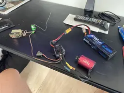
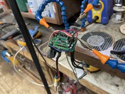
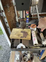
“Fixed” my 45a Tazer ESC by internally bypassing it. Brother was right, somewhere in the board is an open (probably at whatever regulates the power from the lipo batt input down to 5a or whatever it should be at the diagnostic port). Next time we get together he can laugh at my soldering and we can see if we can find the original problem and address it but for now I have what I want back a test mule.


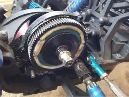
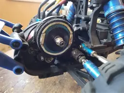
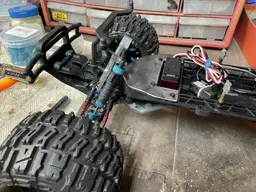
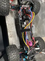
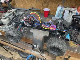
Addressed the camber arms popping off by flipping what side of the rear hub they bolt to. My other choice was to go m3 spacers on the inside mount and that made the angle even harsher. I can go through the whole suspension range of motion without it hitting anything or binding - since I made a change I did end up checking the rear camber and I did need to shorten them up 1/2 turn or so to get back to -2 so that tells me the geometry this way is actually better.

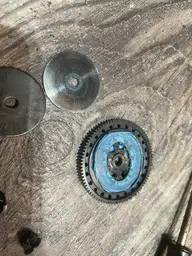
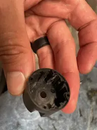
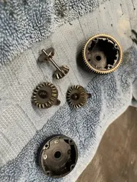
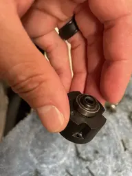
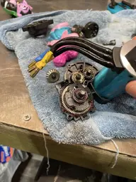
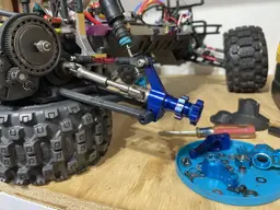
H-R rear hubs are here. God I hate that company but it’s what was already on there, so now I have one spare. That outer bearings was NOT happy lol and came out in about 5 pieces. Ended up with a 0.5 shim on right side and 0.7 on left.


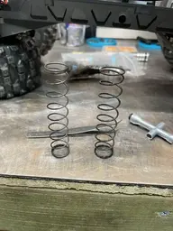
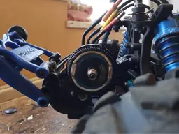
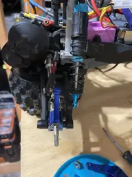
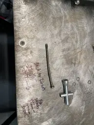
Changed to the 4wd shock (stock length) with 4wd spring in rear mounted in same position. This allowed me to get a even better ride height with one less large preload spacer. We will see how it handles. I think this is more appropriate for the heavier motor, all metal components in back and trans, and wheelie bar. The spring pic compares a 4wd spring (from 110mm shock) to a 2wd rear spring (105mm shock).
Addressed the camber arms popping off by flipping what side of the rear hub they bolt to. My other choice was to go m3 spacers on the inside mount and that made the angle even harsher. I can go through the whole suspension range of motion without it hitting anything or binding - since I made a change I did end up checking the rear camber and I did need to shorten them up 1/2 turn or so to get back to -2 so that tells me the geometry this way is actually better.
H-R rear hubs are here. God I hate that company but it’s what was already on there, so now I have one spare. That outer bearings was NOT happy lol and came out in about 5 pieces. Ended up with a 0.5 shim on right side and 0.7 on left.
Changed to the 4wd shock (stock length) with 4wd spring in rear mounted in same position. This allowed me to get a even better ride height with one less large preload spacer. We will see how it handles. I think this is more appropriate for the heavier motor, all metal components in back and trans, and wheelie bar. The spring pic compares a 4wd spring (from 110mm shock) to a 2wd rear spring (105mm shock).